Optical Time Domain Reflectometry and Phlux Noiseless InGaAs APDs
22nd April 2024
This application guide explains the working mechanisms of Optical Time Domain Reflectometers (OTDRs) and the advantages when developing a system using Phlux Noiseless InGaAs avalanche photodiodes (APDs), or retrofitting Phlux APDs to existing instruments.
Introduction to Optical Time Domain Reflectometry
An Optical Time Domain Reflectometer (OTDR) tests optical fibre network integrity. Hand-held instruments can build virtual images of optical fibres and evaluate their performance and integrity. For example, they can identify where there are connectors, spliced fibres, or bends.
A series of powerful infrared light pulses are injected into the fibre under test. Some of the light scatters (Rayleigh Scatter), some is absorbed into the glass or plastic material of the fibre, and a tiny proportion – perhaps just one-millionth of the level of the original pulse - is returned to the instrument. From this reflected signal, the attenuation of the fibre can be determined, and any faults located.
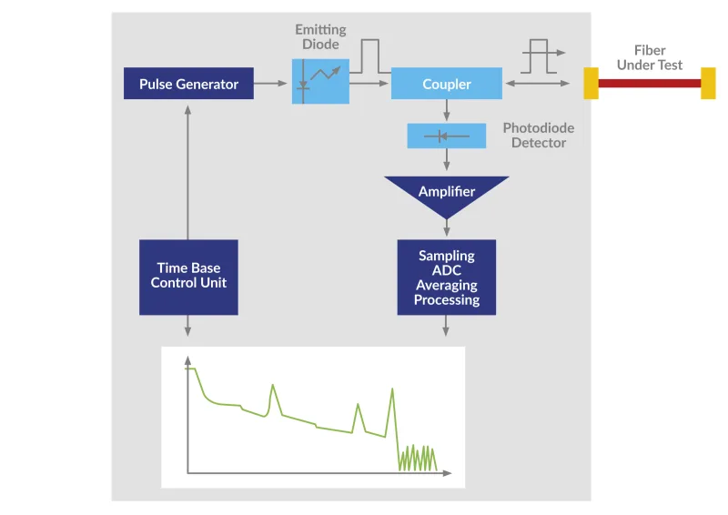
Block diagram of an OTDR and a typical reflection trace (Courtesy of Viavi).
The length of fibre that can be tested depends on the power of the laser diode that generates the pulses, the sensitivity of the infrared detector that captures the reflected signal, and the performance of optical components and signal processing circuits. It also depends on the wavelength of the light pulses. For single-mode fibres, 1310 nm and 1550 nm wavelengths are typical.
Here are some of the things that OTDRs help with:
Ensuring that splices to extend the fibre are well made and not causing attenuation or other problems.
Identifying bends and kinks in the fibre, which are easily introduced as the fibres are handled, even though they are protected to some extent by their sheathing.
Locating breaks in the cable after installation. These can be caused by anything from rodents to roadworks.
Measuring the attenuation along the length of the fibre.
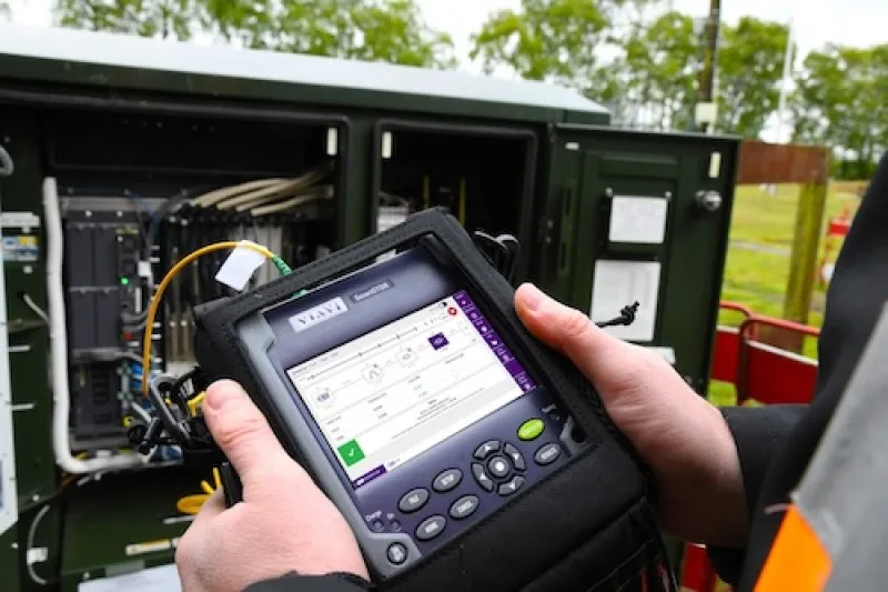
Professional single-mode fibre OTDR (Courtesy of Viavi).
Time domain reflectometry enables the distance from the instrument to any faults to be accurately identified.
If more backscattered light is required for the measurements, the pulse peak power or pulse width is increased. In a handheld instrument, the downside of this is that more power is drained from the battery, reducing its operating life in the field between charges.
For a given instrument sensitivity, the length of the transmitted pulse determines the resolution and the distance over which the instrument can operate. For higher resolutions, narrower pulses are best, but they limit the operating range. For greater range, larger pulses are used, the trade-off being a poorer resolution. Instruments with a 50 dB dynamic range typically have a measurement range of up to 125 km at 1310 nm and up to 220 km at 1550 nm.
What an OTDR trace shows
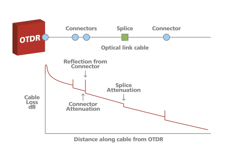
The OTDR displays a trace that shows the signal attenuation along the fibre in dB/km. Connectors and splices will both show a loss, but connectors will also cause a reflection, shown as a peak on the trace. The more light that is reflected, the higher the peak.
The OTDR trace displays reflection and attenuation data
If the peak overloads the sensor in the OTDR, the sensor will take some milliseconds to recover. This means that a second peak close to the first may not register on the instrument. The recovery characteristics of the sensor, which is typically an InGaAs avalanche photodiode (APD), are therefore an important design consideration.
Developments in Indium Gallium Arsenide (InGaAs) APDs for OTDR sensors
For wavelengths from 1100 nm to 1700 nm, where optical fibres have low absorption and dispersion, infrared sensor APDs based indium gallium arsenide (InGaAs) are used. These components exhibit internal gain when reverse biased but until recently, the maximum gain to which they could be set was between about 10 and 40. At higher levels, the noise generated masked the received signal.
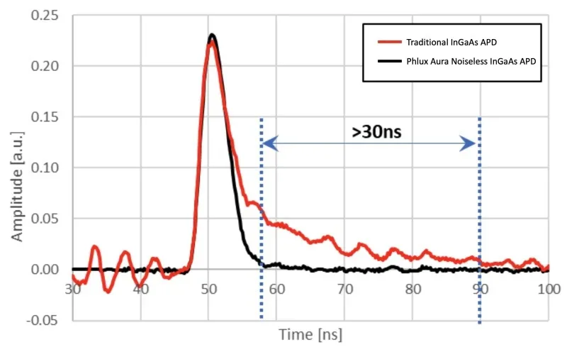
However, a new class of APD, created by adding antinomy alloys to the compound semiconductor process, offers 12X higher sensitivity than components and can operate at gains of over 120. Crucially for OTDR applications, they also exhibit fast overload recovery, significantly reducing 'dead zones' where faults are missed when traditional APDs remain unresponsive due to overloads.
The faster recovery speed of Noiseless InGaAs APDs significantly reduces dead zones in OTDR measurements
OTDR performance and accuracy are further enhanced due to the lower temperature drift than parts without antinomy and exhibit stable high-temperature performance of the new "Noiseless InGaAs APDs".
How replacing an APD upgrades existing OTDR designs
OTDR performance depends on numerous factors, including the type and quality of optics, cabling, interconnect, and active and passive electronic components. For a given design, the performance of the infrared sensor APD is perhaps the most significant determinant of the instrument's usability, range, and accuracy.
Phlux's Aura family Noiseless InGaAs APDs, available in various industry-standard packages, can be used to upgrade current instruments by simply replacing the existing sensors. No other circuit changes are needed. The benefits of doing this include:
The operating range extended by up to 50% or the sampling rate increased by a factor of up to twelve for a given laser power.
Minimisation of dead zones so that more events and smaller event impacts along the optical cable can be detected.
Extended operating life between battery charges for hand-held instruments because the smaller laser pulses, therefore lower laser diode power, can be used for a given range.
More accurate and stable operation in a variety of environmental conditions.
Using Noiseless InGaAs APDs in new instrument designs
For new instruments, lower-power laser diodes may be used without reducing operating range because the Noiseless InGaAs APD sensor is so much more sensitive. This approach reduces the demands on both system optics and thermal management to remove heat from the laser diode and surrounding components. The size of the infrared parts of the instrument can be reduced by up to 30% and costs by up to 40%.
Detailed product specifications for Aura InGaAs APDs are available here.