How Phlux’s Noiseless InGaAs APDs Improve Rangefinders
Introduction
This application guide explains the operation of rangefinders and how they can significantly benefit from using Phlux’s range of Noiseless InGaAs APDs. By using antimony alloy within the APD structures, Phlux has developed an APD with high internal gain and the lowest excess noise. Many laser rangefinder (LRF) systems require a large receiver lens to collect enough photons to overcome the weakness of the return signal. When the Phlux APD is used in a real-world LRF system design it is possible to extend the range by up to 50%, allowing for smaller, lower cost, and more robust devices to be developed.
Operating principle of a laser rangefinder
Range finders determine the distance from the sensor (or user) to a selected point (or object), which can be nearby or tens of kilometres away. Applications include golf; where the user can use the instrument to determine the distance to the green; and military where the user is trying to determine the distance of a target.
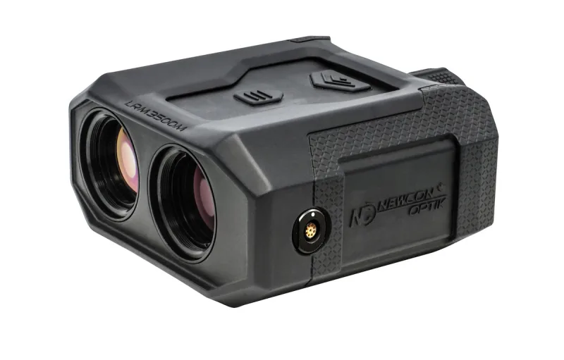
Infrared range finders use modulated infrared light for precise distance measurement and the most popular ones use the Time of Flight (ToF) method to determine the distance. It should be noted that there are other methods for determining the distance, such as phase detection and angle of reflection, these methods are not covered in this note.
The rangefinder emits laser beams at the push of a button. These beams bounce off distant objects and the rangefinder’s accurate timing measures the total time it takes from when the beams left the unit until they returned. Since the speed of light is known, the time measurement can be used to calculate the distance travelled and the instrument displays the distance to the user.
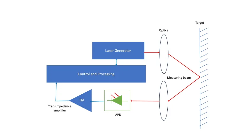
Different LRF applications require substantially different hardware depending upon the desired range and object characteristics. Some have laser diodes pumping out ~100 nJoules (w0 Watts/10 nSeconds) and accumulating or correlating thousands of pulses. Other use fibre lasers and microchip sources with outputs ranging from 2-40 µJoules up to 100 mJoules (near MW peak power) for single pulse detection. The breadth of transmitters creates challenges for receiver designers in several ways:
1. The need to reliably detect pulses with optical return signals that vary from nW to kW/cm2 levels. This demands a dynamic range of 110 dB or more.
2. The need to restore the detection circuit back to maximum sensitivity quickly after a high energy pulse event so that a second signal return close in distance to that of the first can be detected.
3. To generate enough electrical signal to overcome the dominant noise source in most systems - that of the pre-amplifier - whilst not causing false alarms.
Performance comparison of Noiseless InGaAsTM APDs against comparable class-leading devices
Phlux has addressed all these considerations with the Noiseless InGaAsTM technology and has developed an APD product, called AuraTM, for the LRF market. Although existing APDs offer internal gains of 10-20, these come with the penalty of high excess noise factors which degrade the Noise Equivalent Power (NEP) capability and reduce performance. The table shows the relative NEP performances of three different 200 µm diameter APD types when plugged into a 50 MHz/20 kilohm low noise preamplifier LRF reference system. Solar, amplifier, APD, and dark noise are all considered equally between the three APDs:

This indicates that a Phlux APD needs one-third of the photons to achieve a system SNR of 1 when compared to the nearest competitor. Since the NEP needs to be multiplied by 5, for a 99% probability of detection at 0.1% False Acceptance Rate (FAR), the advantages of using a Phlux Noiseless InGaAsTM APD in reducing the LRF design size become evident.
Using the same reference system, the range advantage of the Phlux technology is demonstrated below in the table. The range is given for an SNR of 5 to 1 for the three devices modelled, plus an additional model of a 1st generation conventional InGaAs APD with a gain of M=10.

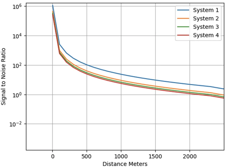
As well as providing range advantages, the Phlux AuraTM APD also enables size reductions, particularly to the LRF receiver objective size. To achieve the same performance as the next best APD, a 2nd generation conventional InGaAs device, the 23 mm receiver lens diameter used in System 1 would need to be increased to 37 mm.
Alternatively, looking at the transmitter power requirements to match the performance of System 1 and System 2, a 500-watt peak power source would need to be increased to 1300 watts.
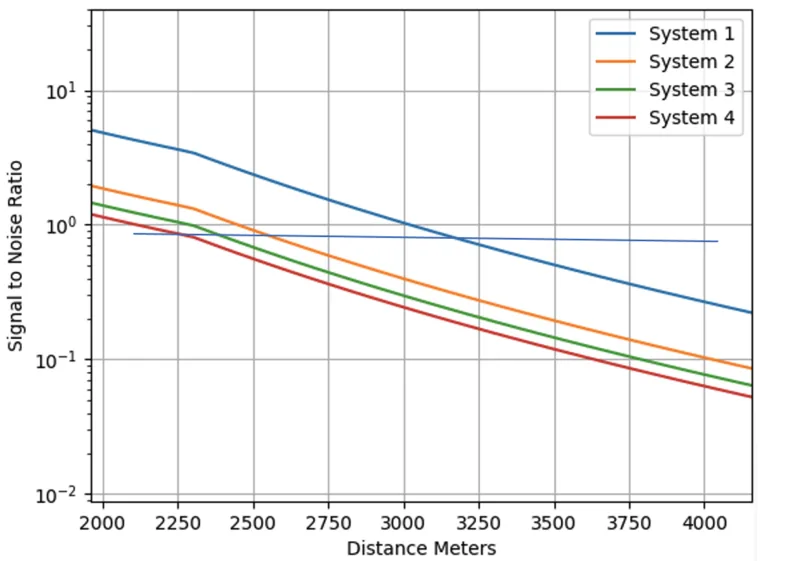
System performance enhancement diminishes in relative scale when pulse averaging or correlation techniques are used. In these cases, the detectable ranges are significantly increased by effectively reducing the equivalent SNR to well below noise floor levels, typically 0.01 and below. This results in the Power on Target falling below 100% of the transmitted light due to the divergence of the laser pulse. For example, a 1 mRad Tx divergent system has a 3 m x 3 m beam size at 3 km whereas the target may only be 2.3 m x 2.3 m. This results in an overfill situation. However, even in these circumstances, the performance advantage of the high-gain Phlux APD provides a typical ~33% increase in the range of a system. This is shown in Figure 4, where Phlux’s Noiseless InGaAsTM Technology (System 1) provides a range of 3,200 m against the next best of 2,250 m (System 2). The downward kink in the returns at 2,300 m is because the R2 Lambertian return is replaced by an element that is R4 in nature. Under some conditions, the range improvement can be as much as 50%.
Overload and recovery characteristics
The overload performance of the receiver is a major concern for designers of LRFs. The detector can experience high power input when an object enters the field of vision too close to the detector. This can happen if someone walks in front of the lens, or the device is pointed at a nearby object. When this happens, the APD must withstand high levels of light input without overloading and the device needs to recover quickly, otherwise the rangefinder will be unusable for a longer period. Figure 5 shows the recovery period for Phlux’s AuraTM APD with a 20 ns input burst, compared to another device with a much longer recovery time.
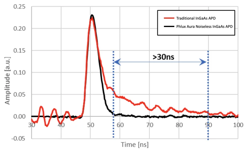
The faster recovery time of the AuraTMAPD ensures that it can detect subsequent reflections occurring from objects just a short distance beyond the one that caused the initial high-level reflection.
Challenges for infrared LRFs
Some of the challenges faced by all free space transmission and detection systems are:
- The performance is heavily dependent on the power launched by the laser. Increasing that has a large impact on size, weight, and system power consumption.
- The light intensity returned by different surfaces differs.
- Oblique surfaces reduce the amount of light signal being returned compared to retro or specular reflectors.
- Solar light conditions and atmospheric conditions such as Rayleigh scatter and water absorption have a significant effect.
All these factors affect the power budget and reduce LRF range performance.
To compensate, LRF developers normally increase the optical budget by increasing the power levels of the laser. This is expensive and can make the LFR a lot larger. However, with Phlux’s Noiseless InGaAsTM APD sensor technology, it is possible to overcome these disadvantages without increasing the laser power. This is because the sensitivity of the APDs is increased, but with low noise, which results in a vastly improved optical budget. With these sensors, it is possible to reduce the laser power, reduce the cost, and increase reliability while still maintaining superior optical performance.
Conclusion
This application note outlines the benefits of using Phlux’s Noiseless InGaAsTM APD and the improvements that can be achieved when using these APDs in applications such as range-finding systems. It shows that by using an APD with Phlux’s Noiseless InGaAsTM technology it is possible to increase optical sensitivity and reduce optical noise thereby enabling rangefinders with increased performance, lower system cost, increased reliability, and hence a more robust application.